What is a linear LED driver
A linear LED driver uses linear, non-switching techniques to regulate the power to an LED or string(s) of LEDs. Linear LED drivers have generated considerable interest in the lighting industry because of their simple architecture, low noise operation, low parts count and reduced circuit size. However, in practice this technology is driving the LED lighting industry to a nasty extreme. The popularity of linear load regulation has been largely spurred by its cost advantage. Manufacturers of entry-level lighting products take this technology as a trump card to undercut their competitors. Today general lighting products that use bare-bones linear driver circuits have become a synonym for dirt cheap, low quality products. Every technology has its pros and cons. Linear driver topology can be a good fit for a number of lighting applications. The problem is that the industry takes this technology as a universal solution for driving down the cost of LED lights.
Driving LEDs
An LED produces light when electricity flows through a p-n junction biased in the forward direction. As the sinusoidal waveform of an alternating current (AC) comprises a positive half-cycle and a negative half-cycle. A forward bias is created only when the sine wave has a predetermined value in each positive half-cycle of the sinusoidal waveforms. This means a line-powered LED will not produce continuous optical emission because it will go out during the negative half-cycle of the AC waveform. Accordingly, the commonly available sources of AC electrical energy have to be transformed into DC power in order to operate the current driven LEDs in an uninterrupted way. Furthermore, the forward voltage applied across the p-n junction must be maintained within a consistently operational range in order for the LED to run continuously. Since LEDs are low voltage devices with the forward voltage varying from 1.5V to 4.5V, the LED module of an LED lamp must be supplied with a matched load. As such, LED drivers, which convert the AC line voltage into a constant current responding to the changing needs of the LED module, become an integral part of any LED lighting system.
AC-DC conversion
In an AC-DC power conversion process, an LED driver begins with rectifying commercial AC mains voltage into an unregulated DC voltage. A DC-DC converter receives a rectified DC voltage and regulates it to provide a desired output. In this process, load regulation provided by the DC-DC converter is of the utmost importance because LEDs must be continuously forward biased at a predetermined voltage to deliver flicker-free illumination. Depending on the mode of operation, the process can be implemented in a single stage or in multi-stages. There’re two techniques used in DC-to-DC power conversion to produce a regulated output voltage from an unregulated input: switching regulation and linear regulation.
What is a switching power supply
Before we get into the topic, let’s have a brief look inside the switched mode cousin of the linear power supply. A switched mode power supply (SMPS) in the context of LED lighting refers to an LED driver that regulates the output to the LEDs through high-speed switching operation. The SMPS LED driver follows boost, buck, buck-boost or flyback circuit topologies to step up or step down supply voltage. One or more power transistor switches between on and off states at a given operating frequency to transform the incoming power supply into a pulsed current. The pulses of current are then smoothed using an energy storage component consisting of capacitors or inductors. There’s minimal switching loss in modern switches such as a metal oxide semiconductor field effect transistor (MOSFET), thus enabling the switching regulator to operate with high efficiency. However, high frequency switching can generate much noise and produce electromagnetic interference (EMI). The use of reactive components as well as the need for additional circuitry to suppress the switching noise makes switching regulators an expensive, bulky, unreliable and technically complex solution to LED load regulation.
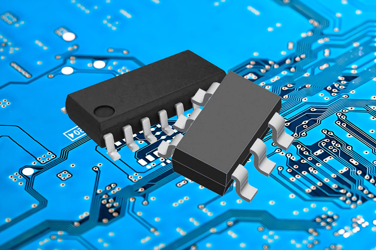
Linear regulators
Compared with SMPS LED drivers, linear LED drivers are on the opposite side. The linear LED driver owes its name to the linear regulator which plays a similar role to a switch regulator in a switching power supply but in a completely different way. A linear regulator operates by controlling the voltage drop across a pass element biased in the linear region, while the switch regulator operates in saturation and cut-off regions of the transistor. Unlike its switching cousin which switches between the full on (cut-off) or off (saturation) mode at high frequency, a linear regulator always operates in the linear region in a partially on mode, with the degree of conductivity determined by a negative feedback loop. By its nature a linear regulator has a fairly straightforward design. It doesn’t produce high frequency switching noise and no energy storage elements are used in the circuit. Therefore, linear regulators pose significantly less design challenges than switch regulators with regard to cost control, reliability engineering and EMI filtering.
How does a linear LED driver work
A typical linear LED driver includes a full wave bridge rectifier, a ripple filter and a linear regulator. Commercial AC power is rectified into DC power and is smoothed out by a low pass filter to achieve a continuous DC voltage with low ripple current. The rectified and filtered voltage is fed to a linear regulator which consists of an internal reference voltage, an error amplifier, a feedback voltage divider and a pass transistor. The error amplifier continuously compares the difference between the reference voltage and the feedback voltage provided by the resistive voltage divider. The pass transistor operates in the linear region to adjust the input voltage to the desired output using the error amplifier. In practices a linear regulator intended for driving a long string of LEDs wired in series often incorporates multiple current regulators which are set with different voltage and current steps. The voltage and current steps are made large for the first regulator and small for the last regulator. This makes the LED load roughly sinusoidal in phase with the power line voltage and thus a high power factor (PF) and low total harmonic distortion (THD) are obtained.
LDO linear regulators
A linear LED driver is very similar to a buck-based switching type LED driver in that they’re both step-down power supplies. In buck circuits, the voltage drop across the regulator cannot be more than 15% of the input voltage. Linear regulators likewise cannot have a high input-to-output differential voltage because this will cause the regulator to dissipate a considerable amount of power. Linear regulators have a minimal input-to-output differential voltage, called dropout voltage, at which the regulator ceases to operate against further reductions in input voltage. Ideally, the dropout voltage of a linear regulator should be as low as possible to ensure a high circuit efficiency and a low thermal load. As the name suggest, a low dropout (LDO) regulator can regulate the output voltage even when the voltage difference between its input and output is very small.
Design specifications
The linear regulator has a number of design specifications to be considered, which include headroom voltage, quiescent current, load regulation (LDR), line regulation (LNR), gain error (GE), power supply rejection ratio (PSRR), transient response, DC accuracy, startup time, and stability. The pass element architecture can affect headroom voltage, quiescent current, and the overall performance. There are two types of pass elements for an LDO: bipolar devices (NPN, PNP) and MOS devices (NMOS, PMOS). Bipolar transistors can produce high output currents for a given supply voltage but their quiescent current is proportional to the load current. The voltage-driven MOS transistors provide very low drop-out voltage and minimal quiescent current. A linear regulator requires an output capacitor to force the gain to roll off fast enough to meet the stability requirements during load transients while minimizing output ripple. The capacitance of the output capacitor and its equivalent serial resistance (ESR) also impacts PSRR. A capacitor with a low ESR and high capacitance helps improve PSRR.
Driver-on-board (DOB)
Rapid advances in linear driver technology gave birth to driverless AC LED light engines which are essentially driver-on-board (DOB) LED assemblies. While the simple architecture of linear regulators substantially reduces the parts count and volume of driver circuits, integrated circuit packaging allows the high voltage switch arrays to be mounted easily on the same printed circuit board (PCB) as the LEDs. Small, surface mount linear drivers ICs overcome the limitations with switch regulators which have large, reactive components and are therefore cannot be mounted on an LED board, a metal-core PCB (MCPCB) with single-sided copper construction. In linear power supplies, the dropout voltage is simply thrown away as heat. An FR4 PCB which is used to mount SMPS circuits obviously will fail to establish an efficient thermal path to dissipate the waste heat away. Driver-on-board technology allows the driver ICs to share the same thermal path with the LEDs, thereby eliminating the need for dedicated driver thermal management. As such, DOB becomes the best mouthpiece for linear driver technology as it enables luminaire designers to build a light engine with a low profile form factor while cutting the driver cost to a bare minimum.
Advantages and applications
LDO solutions are cheap and simple. This is the most eyeball-attracting aspect of this technology. Lighting manufacturers are therefore extremely enthusiastic in using linear LED drivers in their products whenever there’s a possibility. In general, linear LED drivers could be a killer solution for lighting applications where light quality isn’t a top priority but the cost of the lighting products is intensely concerned.
The absence of EMI radiation is one important technical advantage for linear LED drivers. This feature addresses the challenges faced in medical, aeronautical and automotive lighting applications where EMI requirements are very demanding.
Linear LED drivers are inherently more reliable than SMPS LED drivers which use electrolytic capacitors to absorb voltage surges that may be present on the AC line. Electrolytic capacitors are prone to premature failure in high ambient temperatures, which degrades circuit reliability. Linear LED drivers don’t use this bulk energy storage device, instead they use solid state driver ICs to regulate the load.
Most linear LED drivers work with legacy triac dimmers without using additional dimming circuitry. These drivers contain no reactive components, such as coils and capacitors, which present a reactive load to the resistive dimmer and thus causing incompatibility.
Design challenges
Despite all the benefits that come with driving LEDs using linear regulators, the design of a linear LED driver or a DOB light engine involves numerous compromises. The beauty with this technology lies in its simplicity. When more features are required, higher quality lighting is fundamental or strict code compliance is mandatory, linear driver technology loses its glory. The advantages of linear LED drivers are obtained at the expenses of many sacrifices.
Electrical safety
In switched mode power supplies, it is possible to insert a high frequency transformer with primary and secondary windings to block the dangerously high voltages. On the other hand, linear LED drivers have a high-voltage breakdown path through the control circuitry. An LED lamp with power regulated by a linear LED driver relies on the insulation performance of its housing, which is a serious safety concern.
Efficiency and heat dissipation
Operating an LED array with linear LED drivers means that there is always a dropout voltage. A large dropout voltage not only implies a poor efficiency, but also increased thermal stress to the lighting system as the excess electrical power is dissipated in form of heat. As a result, an LED lighting system working in this mode entails an additional thermal capacity to accommodate the heat flux from the driver circuit.
Flicker
In the linear regulation scheme, the load supplied to the LEDs is essentially the intermediary DC voltage that would be in an SMPS-based LED lighting system. A residual of the AC waveform may appear on the output as a variation or ripple. The residual ripple after the rectifier-filter stage causes flicker, a significant detriment to the light quality.
Power factor
To smooth out the high current ripple, a large capacitor on the primary side may be used. However this can reduce power factor requirement because the reactive power drew by the energy storage device distorts the primary-side rectified current waveform. Power factor can also be affected by non-resistive dimming. LED lamps with greater than 5W power rating are required to have a minimum power factor of 0.7, and the PF of all LED power supplies with a power of more than 25W must be greater than 0.9. Oftentimes luminaire designers have to make a tough choice between flicker control and PF compliance.
Input voltage range
Unlike switching power supplies which can be designed to accept a universal AC input voltage (such as 100 to 277 VAC), linear power supplies have a very limited range of supply voltage because they cannot boost the output voltage.


Loading...