Table of Contents Hide
- 1 A Multidimensional Engineering Work
- 2 The Messy Lighting Marketplace
- 3 What Is an LED?
- 4 How Do LEDs Produce White Light?
- 5 LED Packages
- 6 Types of LEDs
- 7 Driving LEDs
-
8
Thermal Management
- 8.1 Thermal droop
- 8.2 Lumen depreciation
- 8.3 Premature system failure
- 9 Optical Control
-
10
Light Quality
- 10.1 Color quality
- 10.2 Light flicker
- 10.3 Glare
- 11 Color Temperature
- 12 Lighting Control
Light emitting diode (LED) technology has rapidly taken center stage in the lighting world. With their advantages of high efficacy, long lifespan, rugged durability, superior controllability and exceptional design flexibility, LED lamps and luminaires (hereinafter collectively referred to as "LED lights" or "LED lighting devices") are already delivering impressive real-world value to virtually every sector. While the lighting industry is leveraging this wave of innovation for new growth opportunities, the complexity of LED technology gives rise to the sneaky business practice of fooling consumers with substandard, entry-level products. Rather than maximizing value delivery to customers through sophisticated engineering and value-packed design or using pioneering technologies, it seems to be a rule of thumb in the lighting industry to gain instant market share by offering killing prices at the expenses of compromised performance, reliability or safety.
A Multidimensional Engineering Work
Consumers who had been on the tiptoe of expectation to reap the benefits of LED technology find themselves lost in a market flooded with products of varying quality. Oftentimes their purchase decisions are made on snap judgments originated from their trust or expectation in the new lighting technology. The fact is LED lighting is much more complicated than conventional technologies. Only with the use of quality components as well as synergistic optical, thermal, electrical and mechanical engineering can LED lights deliver all the benefits that LED technology is known for. Technology is just an enabler, it's how lighting manufacturers design, engineer and manufacture their products that plays a critical role in maintaining the light quality, optical performance and system reliability of LED lights.The Messy Lighting Marketplace
In the history of electric lighting, the transition to LED-based solid state lighting (SSL) is revolutionary. Conventional electric lighting systems relied on either thermal radiation (incandescent and halogen bulbs) using direct line voltage input or gas excitation (fluorescent, metal halide, and high pressure sodium lamps) with power regulated by a simple current limiter (ballast). Today's LED lights are intrinsically electronic systems because their electrical/optical conversion is provided by semiconductor devices and these devices are driven/controlled by electronic circuitry. From electrical devices to electronic devices, the quantum leap in lighting technology is profoundly changing the way we utilize artificial lighting. However, the human world has been difficult to synchronize with the rapid progress in lighting technology:1. The business world seeks nothing beyond profits. Lighting manufacturers strive to simplify system design to cut cost as they did on conventional lighting systems. There are positive aspects in doing so. Reduced product cost could facilitate widespread applications of this energy efficient, environmentally friendly lighting technology. Unfortunately, so far most of the cost-reduction efforts in the lighting industry have not been made through technological advances and engineering improvement, but by continuously breaking the record of acceptable quality limit (AQL), acceptable reliability limit (ARL) and even acceptable safety limit (ASL). Low color quality LEDs, low thermal capacity heat sinks, and bare-bones driver circuits with poor load regulating performance can be frequently found on products available on the market today.
2. What makes lighting manufacturers openly and wantonly produce substandard products is the lack of standards. New technology is still being governed by old standards and regulations. Market access certifications and approvals such as UL, FCC, Energy Star, DLC, CE, CB PSE, RCM and CCC standards either regulate merely the product safety or overemphasize energy efficiency. And even product safety is at stake in markets with no applicable safety standards. Light quality and product reliability are not in the radar of the regulatory authorities. In fact, light quality is equally as important as product safety, and product reliability should be a key component in Return on Investment (ROI) evaluation programs. Light quality components such as color rending performance, temporal light artifacts (flicker), and discomfort or disability glare control are often overlooked. Poor quality light not only affects visual performance, but also may induce negative health effects. In this respect LED lights have far worse performance than the obsolete incandescent lamps. The spectral quality of the LEDs used on most general lighting products is nowhere to be comparable with incandescent lamps which have a light composition similar to the composition of the sunlight. Incandescent lamps have a low flicker percentage (6-11%), on the other hand it’s not uncommon for LED lamps to have a high flicker percentage of 20-30% because the bare-bones driver circuits usually do not have additional components to filter out the flicker.
3. The sneaky business practices from lighting manufacturers parasitize consumer's ignorance in LED technology. LED lighting manufacturers often make ambiguous advertising statements. They claim that their products have a lifespan of 50,000-100,000 hours or 10-20 years. This is very deceptive. What most people don't know is that the figure is in most cases the lifetime of the LED light source. LED life does not equate with the life of an LED lamp or luminaire. Only when its LED light source is paired with characteristically matched LED driver and a high efficiency thermal management system can an LED light have an operation life as long as that of the LEDs. The reliability of LED lights is a serious concern. Poor thermal management and circuit design can accelerate the aging process of LEDs and lead to premature failure of driver circuits. LED lighting manufacturers would never voluntarily improve the light quality of their products because the consumer world doesn't have the awareness and knowledge to criticize their products! Most often, consumer-oriented LED lighting products such as LED bulbs which are typically used in residential settings are made using the lowest cost components and designed with the least reliable circuitry and least efficient heat sinks. These cheap light bulbs usually burn out or blink in a year or two.
We feel obliged to share our knowledge with people. This guide is intended to walk you through every aspect of LED lighting and clear the fog surrounding the LED technology.
What Is an LED?
An LED is a semiconductor device which converts electrical energy into light through a process called electroluminescence. In general, an LED comprises an LED chip (or interchangeably known as LED die) disposed within a package. The LED chip or LED die is basically a two-terminal diode composed of an anode (+) and a cathode (-). It is engineered from a single piece of semiconductor wafer, a thin disk usually made of sapphire or silicon. The semiconductor wafer is deposited with a positively charged (P-type) layer and negatively charged (N-type) layer using a process called metalorganic chemical vapor deposition (MOCVD), which also known as organometallic vapor-phase epitaxy (OMVPE). The positive and negative layers which act as the diode's anode (+) and the cathode (-) respectively are typically made of III-V semiconductors (group III and V elements of the Periodic Table), such as gallium nitride (GaN), gallium phosphide (GaP), gallium arsenide (GaAs), and indium phosphide (InP). The P-type semiconductor layer is doped with acceptor impurities which have fewer electrons in their valence band than the semiconductor material they replace in the intrinsic semiconductor lattice. The N-type semiconductor layer is doped with donor impurities which have a surplus of electrons on conduction band.The junction boundary where the positive and negative layers meet is called a "depletion region", commonly known as "p-n junction". When a p-n junction is formed, some of the free electrons from the N-type layer begins to migrate across the newly formed junction to fill up the holes of acceptor impurities in the P-type layer. The diffusion of electrons and holes produces negative ions and thus creates a reverse electric field between the positive and negative sides. The electric field creates a depletion region that restricts further diffusion of charge carriers unless a forward voltage which is sufficiently large to overcome the reverse electric field is applied across the depletion region. When the diode is forward biased (switched on), electrons "jump" across the p-n junction to recombine with holes and drop into a state of lower energy. The excess energy is released in the form of a photon which essentially is a packet of electromagnetic radiation in the visible range of the spectrum (light).
The wavelength of the light emitted during electroluminescence may depend on the bandgap energy, which is the difference in energy between the conduction band and valence band. LEDs in general require a direct bandgap semiconductor which allows more efficient radiative recombinations of electron-hole pairs than the indirect bandgap semiconductors. The epitaxial layers of LEDs are typically made from gallium based crystals such as GaN and GaP. LEDs made from direct bandgap semiconductors are grouped into two families: the nitride family and the phosphide family. LEDs in the nitride family such as indium gallium nitride (InGaN) compositions have a larger band gap between the positive and negative layers and therefore produce light in the shorter-wavelength (blue and green) parts of the visible spectrum. LEDs in the phosphide family such as indium gallium aluminum phosphide (InGaAIP) compositions have a small energy band gap between the P-type and N-type layers and therefore produce longer-wavelength radiation, visible as amber or red light.
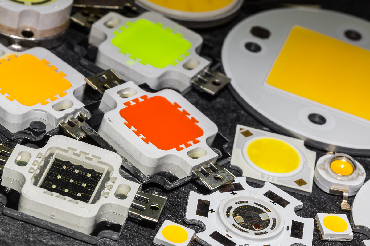
How Do LEDs Produce White Light?
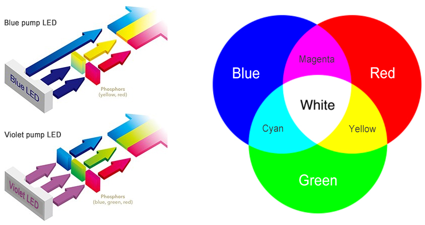
LED chips or LED dies are inherently narrow-band light sources with their bandwidths limited to a few tens of nanometers. The human eye perceives the electromagnetic radiation in a narrow portion of the spectrum as single, deeply saturated colors (red, green, blue). On the other hand, white light that we are exposed to during the day (natural daylight) and we need for nighttime visibility (artificial light) has a wide-band spectrum. To produce white light with spectrally narrow LEDs, one of two methods can be used: phosphor conversion (PC) or additive color mixing.Phosphor-converted (PC) LEDs, which can be found in the vast majority of LED lighting systems, create white light by passing blue light emitted from an InGaN LED through a phosphor conversion layer. The phosphor layer absorbs the higher energy, short wavelength blue light (typically 440–475 nm) and converts part of the blue light to a broad spectrum (yellow). The yellow emission which stimulates both the red and green receptors in the eye is afterwards mixed with transmitted blue radiation, thus creating a combination of wavelengths that is perceived as white by the human eye. The phosphor conversion layer, also called the wavelength converting element (WCE), may be integrated into the LED package or located remotely. Different white chromaticities, such as warm white, neutral white or cool white, can be produced using different phosphor mixes. Compared with LEDs using other types of emission schemes, PC LEDs have four major advantages: high luminous efficacy, simple architecture, chromaticity robustness, and color stability. The highest efficacy white light LEDs today are PC LEDs made from InGaN. PC LEDs that pump phosphors with blue LEDs are also referred to as blue pump LEDs. PC LEDs can be made in other combinations. For example, violet pump LEDs use violet chips to excite 3 phosphors (red, green, blue). The main differences between blue pump LEDs and violet pump are their color rendering performance and luminous efficacy. Violet pump LEDs generally have a color rendition superior to blue pump LEDs, but these LEDs might be less efficient than blue pump LEDs because complete wavelength conversion of violet light generates a substantial amount of Stokes energy loss.
In the color mixing method, tri-chromic (RGB), tetra-chromic (RGBW, RGBA) or even penta-chromic (RGBAW) LEDs are used to create secondary colors. LED chips of at least three primary colors (red, green, and blue) are mounted close spatial proximity. Wavelengths from these color LEDs are mixed together to create a full spectrum white light that stimulates all three types of color sensitive cones (red, green, and blue) in the retina of the human eye. Additive color mixing relies on the use of multi-chip LED modules and requires complex electronics to control individual chips, which is obviously not a cost effective solution for general lighting applications. The RGB method also has a white light efficacy that is significantly lower than PC LEDs. Color mixing LED modules are mostly found in color-changing or multi-color lighting products which are designed to provide flexibility in color output.
LED Packages
In professional terminologies, an LED refers to an LED package, not a LED chip (bare LED die). An LED package is an assembly of one or more LED dies with mechanical supports, electrical connections, thermal conduction paths, and optical encapsulation. The bare LED die is a very sensitive and fragile device that is susceptible to physical or chemical damages. Performance degradation can occur if it is exposed for a long time in an atmosphere of humidity or corrosion. Moreover, the semiconductor die is still a monochromatic light source that must be phosphor coated to produce white light. The purposes of LED packaging are to protect the LED chip from being damaged, to allow the LED to interface electrically and thermally with metal core printed circuit boards (MCPCBs), to enable phosphor conversion within the package (for blue or violet pump LEDs), and to provide efficient extraction of light from the LED.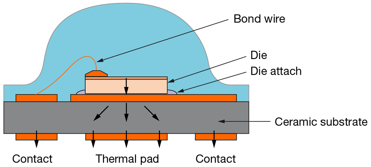
Typical construction of a high power LED (Image courtesy of OSRAM Opto Semiconductors)
A typical LED package includes a carrier substrate which provides mechanical support and thermally connects the LED chips. Mid power LEDs come with a lead frame surrounded by a plastic housing. An electrically conductive layer connects the positive and negative electrodes of the chip to the lead frame or the electrodes of the carrier substrate through wire bonding or die bonding. Wire bonding is the mainstream semiconductor interconnection method which combines heat, ultrasonic energy and force to bond small wires to complete an electrical path and thermal conduction route. The bonding wire material presently used in LED packaging is primarily gold because of its resistance to surface corrosion, high electrical and thermal conductivity, and high productivity through the gold ball bonding process. Because of their relatively low cost, copper and silver are being increasingly used as an alternative interconnect materials. However, wire bonding can limit the packing and power density of LEDs as the wires cap the thermal conduction capacity of the LED packages. Flip-chip packaging allows the die to be soldered directly to a substrate without the need for bond wires. As such, the LEDs can be driven at a higher current density and more compact designs are achievable.

Typical construction of a mid-power LED (Image courtesy of OSRAM Opto Semiconductors)
An LED package has an encapsulant formed on the substrate to cover the LED die and down-convert some of the short-wavelength light emitted by the LED (phosphor conversion). The encapsulant is typically a mixture of a wavelength converting element such as a YAG:Ce phosphor and an organic polymer. At present, most of the mid-power and all of the high power LED packages use silicone polymers for phosphor encapsulation for their advantages in high thermal stability, high optical transparency, high refractive index, and good adhesion. The encapsulant is dispensed on top of the LED die and is then cured into a transparent solid layer that protects the LED. Along with phosphor encapsulation, an optical element such as a hemispherical lens can be mounted as a part of the package to enhance light extraction and possibly to provide beam control.
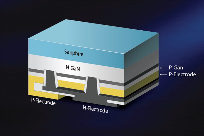
Samsung flip chip LED
LED packaging is a critical process that fundamentally influences the thermal performance, color quality, optical efficiency and lumen maintenance of an LED. Depending on the device type, packaging can account for 40% to 60% of an LED's total cost. Top LED manufacturers like Cree, Osram, Nichia, Lumileds and Seoul Semiconductor invest heavily in packaging technology and device design. In conjunction with in-house production that ensures tight process control and the use of high quality components and materials, their products deserve a good brand recognition. In general, you can't go wrong with using light sources from trusted brands. On the opposite side, there're a number of undependable LED packaging suppliers whose products have poor color performance and are highly prone to bonding failure and phosphor degradation.
Types of LEDs
Selection of an LED package architecture depends on the light output, optical design, form factor, and application scenario of the lighting system. There are four main LED package platforms that are being used as light sources for LED lamps and luminaires:Mid-power LEDs (0.1 to 0.9W) are the universal choice for applications where high density or high center beam candlepower (CBCP) lighting is not required, and other factors such as cost, efficacy, and LED mounting flexibility are more of a concern. They are typically used as light sources for LED lamps, linear light modules and interior light fixtures such as light bulbs, light tubes, ceiling lights, troffers, wall lights, channel systems, edge-lit LED panel lights, and LED strip lights. The main challenge with mid power LEDs lies in their limited thermal performance because these LED packages use plastic resin such as polyphthalamide (PPA) or epoxy molding compound (EMC) as the package substrate. At high drive currents and long operating times, the plastic resin substrate can discolor, crack or delaminate, resulting in lumen depreciation and color shift.
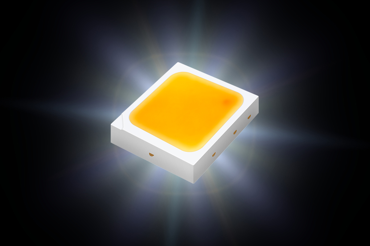
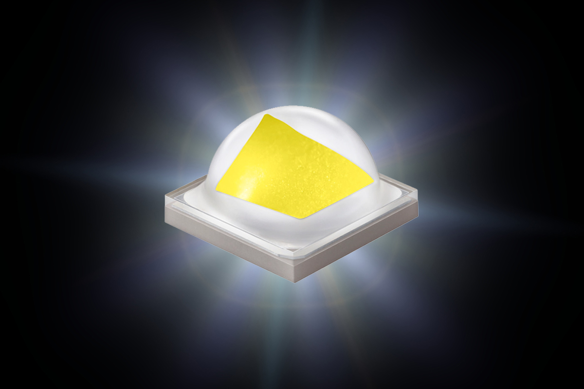
High-power LEDs (1 to 5W) are high lumen density light sources that deliver an impressive amount of light in a small package. They provides a solution for a diverse range of outdoor and industrial applications such high bay lighting, flood lighting, street lighting, and stadium lighting. The high-power LED architecture either uses a large die or numerous small die in series to create a high voltage package. LED dies in high power packages often produce considerable amount of heat produced around the junction area of the LED. High optical flux density also induces substantial thermal stress to the phosphor and binder materials because the wavelength conversion undergoes the Stokes shift. To facilitate heat dissipation, the LED is mounted onto a ceramic substrate which acts as a high efficiency heat spreader. With efficient thermal management, high-power LED packages typically have a better lumen maintenance than mid-power LEDs.
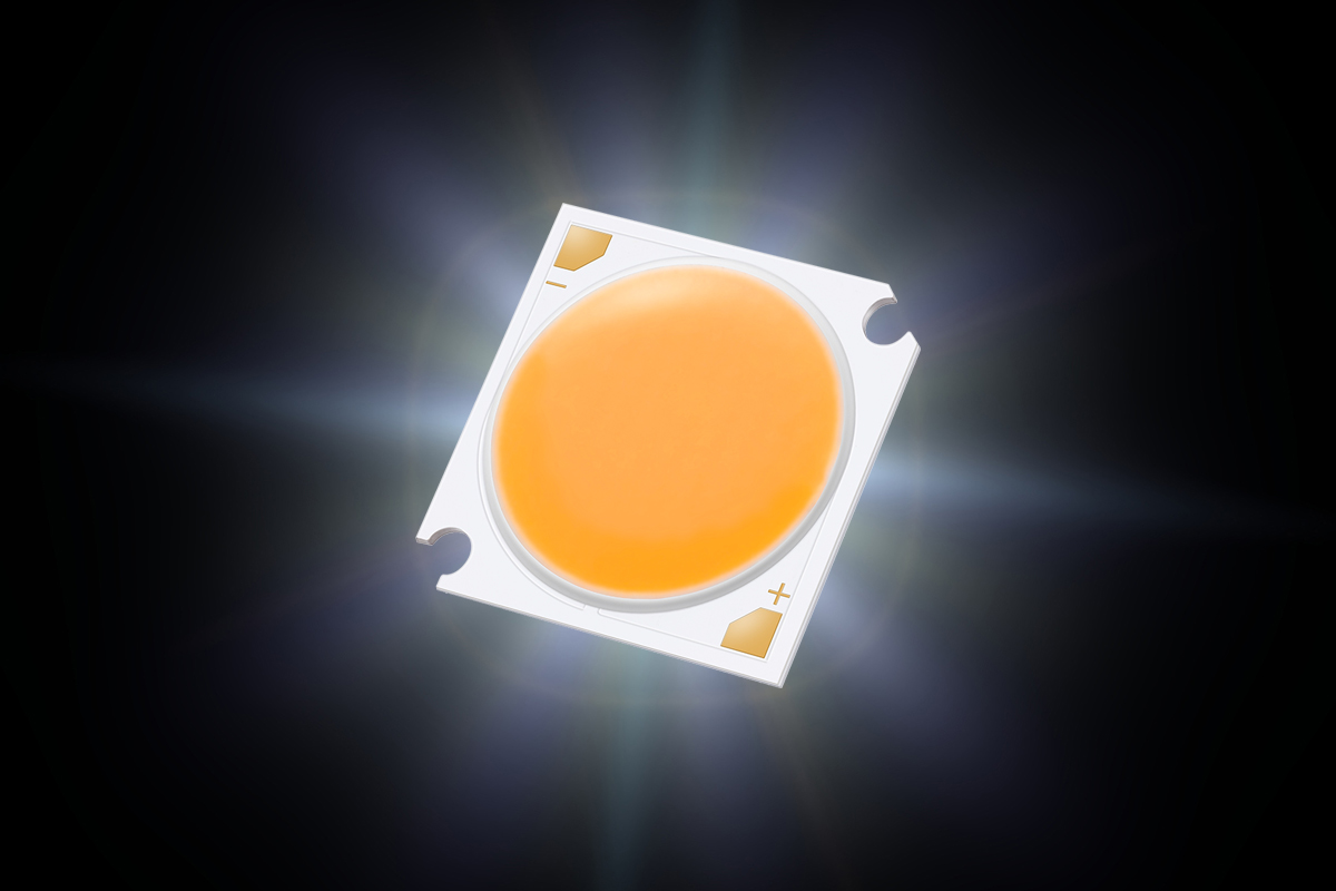
Chip-on-board (COB) LEDs are designed to deliver high CBCP or "punch" for directional lighting applications in commercial showrooms, retail stores, hospitality spaces, museums, art galleries, and high end residences. COB LEDs are primarily used in recessed downlights, track lights, directional spotlights and floodlights, and other luminaires that require precise beam forming and uniform illuminances. In a chip-on-board package, a large array of small die mounted onto an MCPCB or a ceramic substrate to produce a high power density. The phosphor coating is applied across the entire array for a uniform chromaticity and output. Direct interfacing with an MCPCB or a substrate with low thermal resistance allows the high density LED array to provide a robust thermal conduction path to dissipate heat efficiently from the junction to the heat sink.
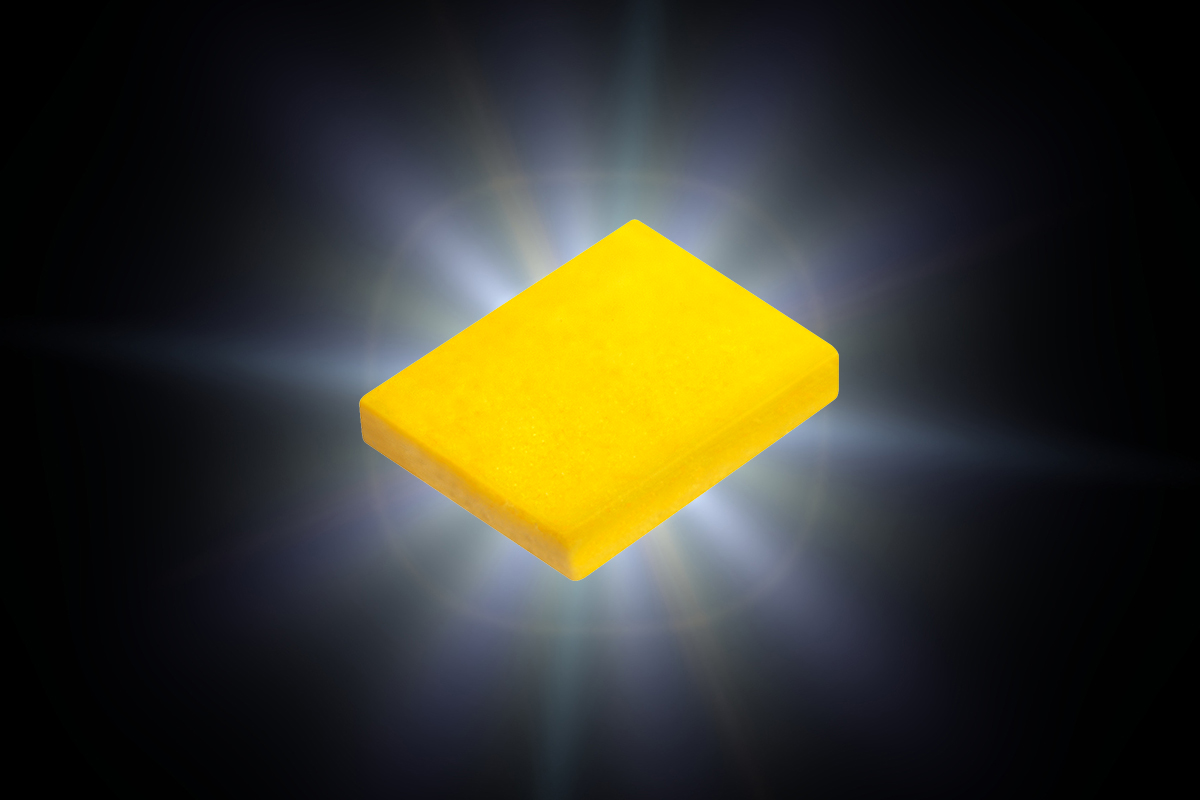
Chip scale package (CSP) LEDs are package-free LEDs with their metallized P and N contacts directly soldered onto an MCPCB. This eliminates the traditional submount for attaching the LED die to a lead frame or ceramic substrate via wire bonding and therefore reduces the thermal resistance between the LED die and the MCPCB. CSP technology significantly scales down an LED package to a footprint approximately the same as the LED die, enabling more flexible and compact designs of LED modules and light fixtures. A CSP LED generally uses the flip-chip die as a base onto which phosphor deposition can be applied by via various methods such as coating, screen printing, spray deposition, immersion and film lamination.
Driving LEDs
An LED is a semiconductor diode that conducts electricity in only one direction. When a forward bias is applied across the p-n junction, electrons and holes recombine to emit light. If the diode is reverse biased (anode negative with respect to cathode) it will resist current flow and no electroluminescence will occur in the p-n junction. If the negative voltage exceeds the reverse breakdown voltage of the LED an immediate degradation and consequently a permanent damage can occur on the LED. Therefore the LEDs have to be supplied with a direct current (DC), rather than an alternating current (AC) which has a sinusoidal waveform with its positive and negative half-cycles switching at a sinusoidal frequency of 50 or 60 Hz. Since the electrical power grid delivers an AC voltage, power supplied to the LED must be converted to DC for a constant forward current. The forward voltage of an LED is very low: 2V to 3V for InAlGaP LEDs (red, orange and amber) and 3V to 4V for InGaN LEDs (green and blue). The supply voltage must be stepped down in order to operate an LED or a string (or strings) of LEDs.An LED driver is an electronic device that regulates the power to the LEDs. It converts AC power into DC power with outputs matched to the electrical characteristics of the LEDs, over single or multiple channels. An LED driver typically uses a rectifier to convert commercial AC power into DC power, a ripple filter circuit to remove ripples which are residual periodic variations of the direct current output, and a power converter circuit to step down the DC power corresponding to an LED load. LED drivers can be designed to provide either constant voltage (CV) or constant current (CC) output. A constant current driver provides a fixed output current (e.g. 350mA, 700mA or 1050mA) at the driver level to ensure minimal variations in forward voltage across the entire LED load, irrespective of the number of LEDs that consume this load. A constant voltage driver provides a constant DC voltage output, typically 12V or 24V, to a number of LEDs or LED modules that are configured mostly in parallel connection. Each LED or LED module comes with its own linear or switching current regulator to limit the current in order to maintain a constant output.

Switched mode power supply
In a typical load regulation process for LED lighting, the LED driver converts the AC line voltage into a DC voltage by rectification. A DC-DC converter receives the rectified DC voltage and produces a DC output that corresponds to the current design requirements of the LED load. The DC-DC power conversion is usually provided by a switched mode power supply (SMPS) (also called switching regulator). The switching regulator generates the predetermined magnitude of DC power through "0/1" (ON/OFF switching) modulation. There are many circuit topologies for SMPS, including boost, buck, buck-boost and flyback. Switching regulators in general deliver high power efficiency and allow a wide range of AC input voltage (e.g., universal input voltage 120-277VAC 50/60Hz). However, the high-speed switching operation of SMPS drivers relies on reactive components such as inductors, capacitors and oscillating coils. This can generate high frequency noise and electromagnetic interference (EMI) that has to be suppressed by advanced circuit design, screening, and filtering. As such, the component counts and circuit complexity are increased.Linear power supply
Linear power supplies regulate the DC voltage on resistive loads. They can be as simple as a voltage regulator which includes an operational amplifier and an NPN transistor (power switch). A feedback resistor is connected between the output and the adjust pin so that a voltage drop can be sensed when current flows through the resistor. The operational amplifier controls the NPN transistor to limit the current when the voltage drop reaches a minimum input to output voltage difference. Although these is the cheapest and simplest solution, a substantial amount of heat can be generated because of the poor efficiency. Advanced linear regulators use a combination of both ICs and discrete devices to achieve higher efficiency and also trim off the ripple with low levels of EMI and a good power factor (PF). However, the efficiency of a linear LED driver, which is the ratio of the load voltage to the supply voltage, is generally considerably lower than SMPS LED drivers. The supply voltage range of linear LED drivers is significantly limited because the load voltage must be kept below the supply voltage. Nevertheless, linear power supplies have a number of advantages, including low cost, immunity to EMI, simple design and high circuit reliability.Power utilization
Power factor correction (PFC) of LED lights is nothing to do with end-users but means a lot to lighting manufacturers. The power factor (PF) of an AC electric power system refers to the ratio of power utilized to power delivered and is expressed either as a number between 0 and 1. A power factor of 1.0 means that the load is using all power being delivered by the utility company. Only when an LED load draws current exactly in phase with the power line voltage can a PF of 1.0 be achieved. This would be a purely resistive load. A PF of less than 1 indicates that part of the power is wasted and may return power to the utility power grid out of phase. To supply a load with a low power factor, the utility needs to generate more than the minimum volt-amperes necessary in AC power, this causes its infrastructure to operate above capacity.
Most LED drivers are designed as switched mode power supplies which include reactive components. The reactive components will produce inductance and capacitance that can lead to phase difference between the input voltage and the input current, and consequently a reduced PF. In many countries there are regulations on minimum PF requirements for line-operated equipment. A European standard requires LED lighting systems with a power consumption more than 25W to have a PF higher than 0.9. For this reason, SMPS drivers must employ some form of power factor correction to shape and time-align the input current into a sinusoidal waveform that is in phase with the source voltage.
Total harmonic distortion (THD) of the input current waveform is another concern for utility companies. High THD in distribution networks can lead to overheating in neutral conductors and distribution transformers, result in failure or malfunction of electrical equipment and protective relays, and also interfere with communication transmission lines. The THD of line-operated equipment, including LED luminaires for commercial, industrial and outdoor applications, should be kept as low as possible. A THD value below 20% across the entire input voltage range of an LED luminaire is usually acceptable to various standards and regulations, and a THD of less than 10% would easily meet the requirements of the most stringent energy programs. The distortion in the current waveform is caused by non-linear electrical loads. Harmonic distortion does not occur in true resistive loads, but is found in electrical equipment containing reactive elements. This implies an improvement in PF can reduce harmonics as well.
Electrical safety
Line-powered LED drivers designed for AC mains applications can be generally classified into isolated type and non-isolated type. Isolation is used to block the transfer of high or hazardous voltages between circuits to prevent injury to the human body due to electrocution and damage to an electrical circuit resulted from unintended electric current. This process of blocking hazardous voltage potentials is referred to as galvanic isolation. The output circuit of an isolated LED driver is galvanically isolated from the AC mains. The galvanic isolator is typically a transformer which has its primary winding or mains connection side insulated from the secondary winding while buffering or changing voltages using magnetic field flux generated by coils of wire.The use of an isolation transform adds to the overall cost of the circuit and reduces the available circuit space. This leads to proliferation of non-isolated LED drivers in which a high-voltage breakdown path exists through the driver circuitry. In this case, extra caution should be taken because the electrical safety of LED lights using the non-isolated topology solely relies on insulation between live and accessible parts.
Poor design can also result in electrical shock hazard or circuit damage. Short creepage distance can cause electrocution or fire. Arcing between electrodes caused by the ionization of air can occur when there's no sufficient clearance between two conductive parts.
Thermal Management
The performance and lifespan of LED lights depend to a high degree on their thermal management. Heat is a disturbing byproduct of LED lighting. When electrical current is passed through the semiconductor junction, only less than 60% of the electrical energy is converted into light and the residual energy is released as heat. The phosphor conversion process of blue-pump LEDs also produces heat. Typically, about 15–30% of the blue photons absorbed by the phosphor is converted to heat as a result of the Stokes shift. The thermal stress on an LED lighting system can be compounded by a co-located driver which converts around 10% of the AC power into heat. Low efficiency circuits, such as driver-on-board (DOB) linear regulators, can produce a substantial amount of heat that has to be dissipated.What if there is poor thermal management? A number of failure mechanisms will be accelerated.
Thermal droop
Thermal droop refers to the reduction in the optical power in correlation with the increase in temperature. The junction temperature of the LED should be typically maintained in the 70°C to 100°C range. Beyond the maximum rated junction temperature, InGaN LEDs can lose up to 25% of their optical power. Thermal droop is more severe for AlGaInP LEDs, the optical power of which can drop up to 70% in elevated junction temperatures.Lumen depreciation
LED lifetime is measured in lumen maintenance which refers to the ratio of a light output of an LED to its initial lumen output. Since lumen depreciation to 70% of initial lumen output is generally considered the lowest limit for most lighting applications, L70 which is time in hours at which the LED light output depreciates to 70% percent if its initial value becomes the generally accepted lifetime metric. Continuous operation at elevated temperature dramatically accelerates irreversible lumen depreciation of an LED. Every 10ºC increase in junction temperature will lead to 30% to 50% decreases in its useful life.Color shift
Increases in junction temperature will narrow energy bandgap between the conduction and valence bands of semiconductor layers, this in turn increases the wavelength of the light emitted by the LED and alters the color output. This is just a reversible color shift. Higher temperatures will accelerate phosphor and encapsulant degradation. This can result in permanent chromaticity changes which can be even more offensive than lumen depreciation.
Premature system failure
Most LED driver circuits use electrolytic capacitors to absorb voltage surges that may be present on the AC line. When exposed to heat, the electrolyte in the capacitor will evaporate at higher rate until it eventually loses its capacitance. As a result, the driver is the first component of an LED lighting system to fail. By and large, the lifetime of an LED light is determined by the reliability of its driver, rather than the LEDs which are intrinsically reliable and rarely fail abruptly.Thermal management for LED lighting systems calls for a total system approach. Aside from operating the LEDs with an optimal drive current to prevent excess thermal conversion, an efficient thermal conduction path from the die to the ambient environment must be created. The thermal resistance of the components along the thermal path needs to be reduced to a minimum to ensure the junction temperature is kept low under all drive and operating conditions, while other thermally sensitive components and circuits are not loaded with waste heat. Substrate thermal conductivity of LED packages, solder joint reliability, MCPCB performance, thermal interface material (TIM) characteristics, thermal stability of circuit components, and heat sink design and construction are all essential elements to be considered in a thermal design.
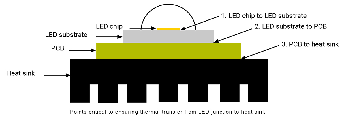
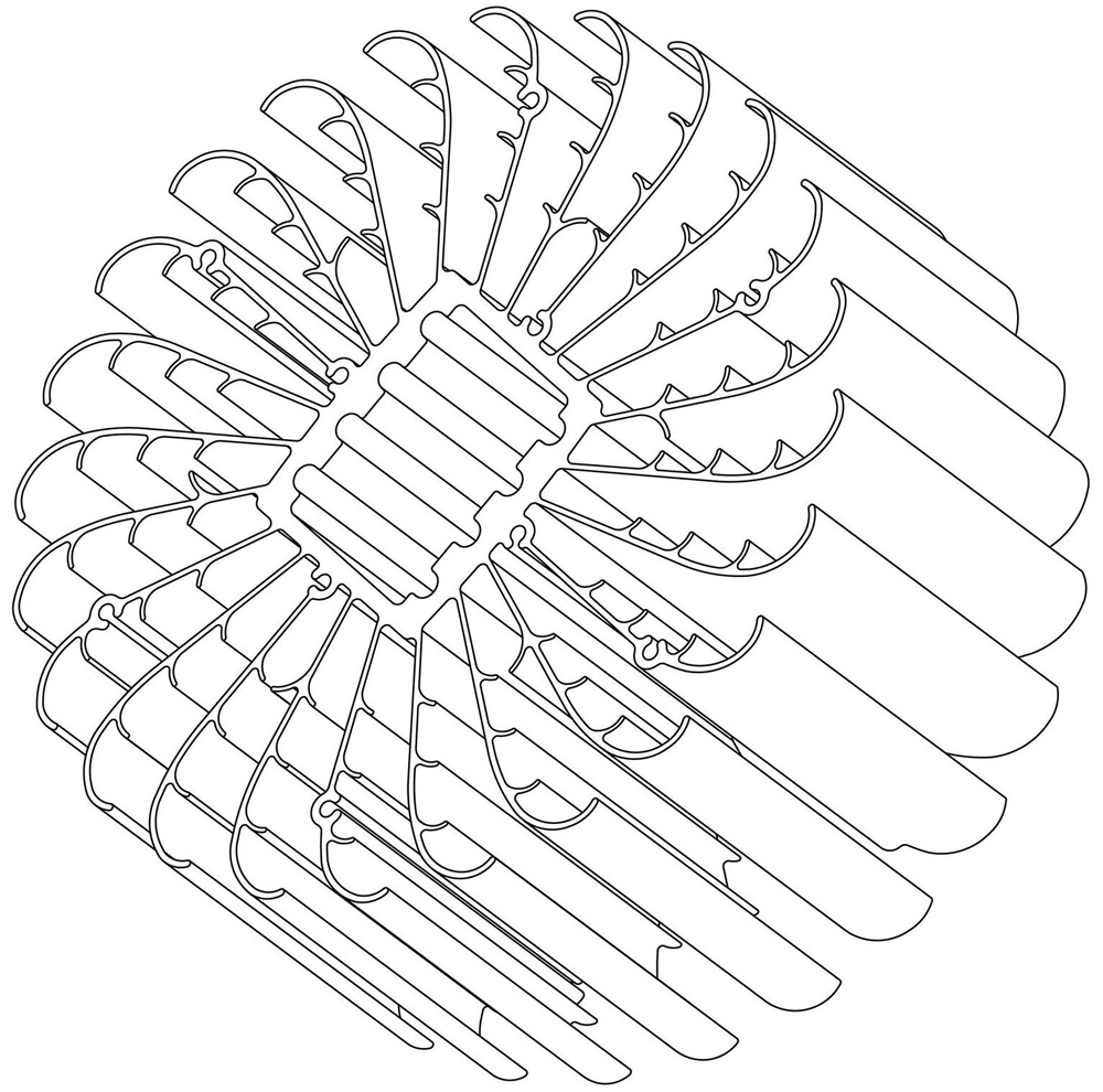
Thermal management on the system level (heat transfer from the MCPCB to the surrounding environment) is typically provided by a heat sink. The primary function of a heat sink is to conduct heat away from the MCPCB and then to convect and radiate heat to the ambient air. Heat sinks can be made from a variety of thermally conductive materials such as aluminum, copper, stainless steel, polymers, and ceramics. Various methods are used to fabricate metal heat sinks, including die casting, forging, extrusion, stamping, bonding, folding, skiving and machining. Most heat sinks for LED luminaires are manufactured through die casting, forging or extrusion using aluminum alloys. In addition to using materials with high thermal, maximizing the effective surface area and the convection heat transfer coefficient is an integral part of thermal engineering. Channels, fins or other geometries are often built into the heat sink to increase surface area. Some heat sinks are designed with aerodynamics in mind to facilitate convective heat transfer.
When the thermal load of an LED lighting system is too high to be managed by passive heat sinking, active cooling technologies including fans, heat pipes, thermoelectric coolers, or other heat transfer systems can be employed to provide additional thermal capacity. Forced convection provided by electric fans effectively addresses thermal management challenges posed by lighting system designs which leave limited surface areas for passive cooling. High wattage LED bulbs, mogul base retrofit lamps, automotive headlight bulbs, and high output light fixtures such as LED grow lights often use fans to lower the convective thermal resistance within the lamp or luminaire.
Optical Control
An LED lamp or luminaire is typically equipped with secondary optics to modify the output beam of the LEDs, regulate the distribution of luminous flux, and eliminates visible hot spots from pinpoint LEDs to provide visual comfort. Secondary optics can also be visually integrated into the lighting system to serve an aesthetic purpose. Optical design for LED luminaires is challenging yet exciting. Unlike conventional light sources that provide limited design flexibility, the directionality, solid state property and compact form factor of LEDs open up a host of possibilities for optical control. LED secondary optics include lenses, reflectors, refractors, diffusers, and light guides. Shades, baffles and louvers are also used in some applications to reduce or eliminate the direct view of the LEDs from outside the luminaire. There are many materials out there to be considered when designing optics for LED lighting systems. Important material properties include design flexibility, transmission efficiency, reflective characteristics, refractive index, thermal stability, ignition Resistance, impact Resistance, chemical resistance, and UV stability.Optical lenses travel through at least two surfaces and focus or diverge light efficiently than reflectors. The most common lenses in conventional lighting are Fresnel and prismatic lenses. The advent of LED technology gave birth to total internal reflection (TIR) lenses which appeal to a wide range of lighting applications for their high optical efficiency, excellent beam controllability and smaller physical size. TIR optics, which have a refractive lens molded inside a reflector, combine the lens' excellent light-gathering ability for the rays at a small angle and the reflector's advantage in converging the rays at a large angle. TIR lenses can manage both direct and reflected rays for precise light distribution and uniform illuminances. Lenses are generally made from glass or transparent plastic. Most of the TIR lenses are manufactured from polycarbonate (PC) or polymethyl methacrylate (PMMA).
Reflectors include elliptical, zonal, hyperbolic, parabolic, and non-conic reflectors. Conic reflectors are usually self-flanged to eliminate light leaks and regulates luminous flux from the light source through mirror reflection, diffuse reflection, and a mixed combination of them. Metal reflectors are polished or chemically coated to produce a specular finish. Reflectors can also be faceted or segmented to improve beam uniformity. Reflectors work well when the light source is omnidirectional and are preferred in spaces where high intensity light is needed. However, they do not offer as much control for directional light sources as LED lenses and therefore are often used in conjunction with lenses to optimize light distribution.
Diffusers are light control elements that can be used over the entire LED array to scatter and redirect incident light in many directions. A diffuser produces diffuse-scattering through its material to destroy optical images, obscure the interior of luminaires, suppress diode images, and reduce high luminances (glare) by increasing the area over which light leaves a luminaire. Opal diffusers create light intensity distribution curves (LIDC) to distribute luminous flux from light source evenly to all directions. Gaussian diffusers typically come with a sandblasted surface on which the high intensity LED rays are diffused into various directions. Prismatic diffusers are molded with geometric structures such as pyramids, hexagons, spherical domes, and triangular ridges to change the distribution of luminous flux in the most desired LIDC so as to avoid high luminances. Prismatic diffusers are also called refractors.
Light guides are used for transporting and distributing luminous flux homogeneously over longer ways and/or for redirecting light into other directions through total internal reflection (TIR). The working principle of a light guide is based on Snell's Law which describes the interaction of light with a material e.g. glass or plastic: when light rays travel incident to a boundary between two mediums, they bends or refracts at the boundary. One of the most well-known lighting products that uses light guide technology is the edge-lit LED panel light, an LED alternative to troffers. An LED panel light uses a light guide plate (LGP) to efficiently extract the light from arrays of edge-mount LEDs and uniformly distribute the luminous flux over the entire surface of the panel to deliver homogeneous illumination. LGPs are usually made of PC or PMMA.
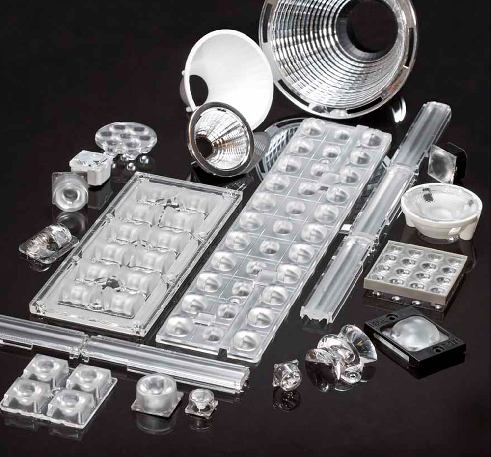
Image courtesy of Ledil Oy
Light Quality
Good lighting is vital for vision, activity and perception. The quality of illumination directly affects our ability to interpret the environment around us and interact with objects in the space. Few environmental elements influence our task performance, visual comfort, aesthetic judgement, social communication, health, safety and well-being like lighting. Light quality is a paramount concern in the era of LED lighting which has too many trade-offs between cost and light quality. The color quality of LEDs, the driver's ability to reduce temporal light artifacts (TLAs) and the luminaire's optical design to soften the harshness of LEDs are all critical components that contribute to an excellent composition of light. Unfortunately, light quality is often compromised for the lowest possible price. This is a lose-lose market. Lighting manufacturers have pitiful profit margins because of heavy competition and consumers have been unconsciously paying for poor quality light. Let's see how light quality of LED lamps and luminaires is being compromised.Color quality
The ability of a light source to faithfully reproduce the color of various objects is referred to as color rendering or color quality. Color quality is currently defined by a flawed metric called Color Rendering Index (CRI) which was established by the International Commission on Illumination (CIE). This color fidelity metric quantifies the relative color quality of an artificial light source with respect to a theoretical blackbody radiator or natural light. CRI is calculated using only eight pastel colors which are all of low to medium chromatic saturation and do not cover the entire range of visible colors. This means that the CRI calculations do not factor in the ability of the light source to properly render highly saturated colors such as red. As a result, LEDs measured by this system can render colors of low saturation well, but may perform poorly with highly saturated colors.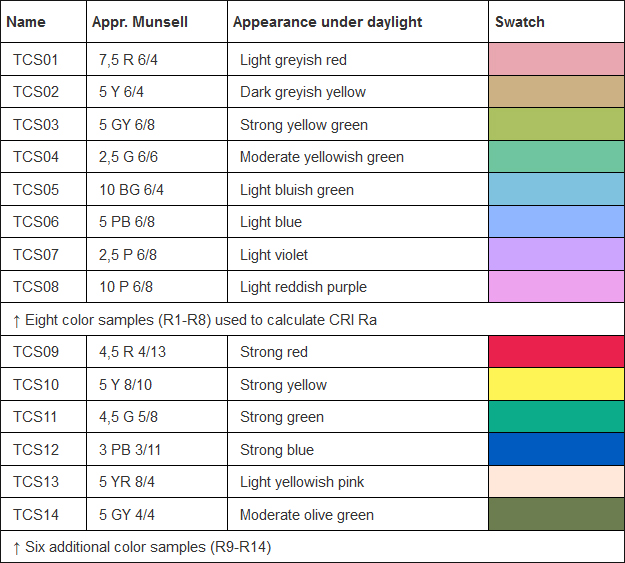
Even with the CRI calculations, most LED products that are selling to general consumers have a disappointing value. CRI is the averaged result of the color rendition measurements of the eight color samples, and the CRI calculation is technically known as Ra with 100 being the highest score. The CRI of the highest quality light, natural daylight, has an Ra of approximately 100. The obsolete incandescent bulbs have an Ra greater than 95! What about LED lights? The CRI of interior LED lighting products is typically 75-85! The higher the color temperature or the cheaper the products, the lower the CRI of the LEDs have. Lighting technology is advancing, light quality is deteriorating. Low CRI lighting today is a consequence of fluorescent lighting which is terribly poor in color reproduction. LEDs can be formulated to emit with a light spectrum comparable to natural daylight. As mentioned previously, lighting manufacturers are not pushed to incorporate high CRI LEDs in their products because there's no consumer awareness and the use of high CRI LEDs would undermine their cost-competitiveness.
Poor CRI means a light source omits part of the spectrum, which makes everything in a space appear dull or lifeless like a fluorescent lamp. Lack of highly saturated color components in the radiometric emission spectrum makes skin tones appear less healthy. Low CRI LEDs fail to bring out the rich colors in artwork, fabrics, and the home decor. Visually demanding tasks, including reading tasks and detail work as well as all activities involving color selection or design, rely on high color fidelity lighting. In general, light with a minimum CRI of 90 is necessary for residential interiors. CIE R9 (for red color rendering) begun to be emphasized for general LED lighting to correct the problem with the flawed CRI standard. Commercial applications, e.g. the hospitality industry, high end retail stores, museums and galleries, are extremely picky about the color performance of a light source and require the right amount of spectral content in every wavelength within the visible spectrum of white light (400 - 700 nm).
Cheap blue pump LEDs are present in many entry-level interior lighting products such as LED bulbs, LED tubes, LED troffers, and flush mount ceiling lights. The phosphor coating for these LEDs serves only to convert perceptible whites and is made using the lowest cost formulation. High color rendering LEDs use a mixture of phosphor that can excite a broader spectrum of light and thus involves a higher cost. High quality white light can also be created by violet pump LEDs. The light emitted by the violet-producing chips is downconverted by a phosphor mix that contains red, green and blue phosphors. These high color fidelity LEDs are designed for high end lighting applications and are rarely found in residential lighting products. The question is: shouldn't we deserve good lighting in our living spaces?
Light flicker
Again, you'll miss the days of incandescent lighting if you were told many LED lamps perform poorly with regard to low flicker lighting while you could never be wrong with any incandescent bulb in this respect. Incandescent and halogen lights have minimal flicker because they, like the sun, are thermal radiators. LEDs operate through high frequency on/off cycles which fuse into a steady and continuous source of light with the intermittent intervals imperceptible to the human eye. Unlike thermal radiators which have a relatively long persistence, LEDs have no or very short persistence by nature and need a constant current flow to maintain their smooth output. Any change in forward current supplied by an LED driver can lead to a virtually instant change in light output of the LEDs. That's why the performance of LED drivers is critical to an LED lighting system.Flicker and other TLAs (stroboscopic effect, phantom array) in LED lighting can be caused by voltage fluctuations in AC mains, residual ripples in the LED load, or incompatibility between the dimming circuit and LED driver. Most often, LED flicker is not visible to the human eye because it typically occurs at frequencies above 80 hertz (Hz). Although not noticeable, the high frequency flicker can still have unwanted side effects. Prolonged exposure to flicker will severely strain the human eye and causes fatigue, blurred vision, and reduced visual abilities to people working in such environments. In certain populations flicker can be a trigger for migraine headaches and photosensitive epilepsy. The hazardous phantom array effects produced by high frequency flicker may lead to distraction when driving at night. To stay safe, flicker below at least 400Hz should be controlled within a tolerable limit.
A high performance LED driver provides excellent load regulation to deliver low flicker lighting. Most or all of the interharmonics of rectified signals and the residual output ripple can be filtered out using ripple suppressors. However, cost and form factor restrictions have the biggest say in driver circuit design. Since there're no regulatory requirements on flicker, few LED lighting manufacturers take it as a top priority. As a result, the circuit architectures of SMPS LED drivers are simplified to a maximum and flicker mitigation is compromised. Linear LED drivers which were born to serve the entry-level markets usually have the highest flicker percentage - around 30 percent at 120 Hz, while the Illuminating Engineering Society (IES) suggests that 10 percent flicker at 120 Hz should be the upper limit.
Glare
One of the primary purposes of optical design for LED lighting systems is to reduce glare. LEDs are high intensity light sources which can provoke more discomfort than conventional light sources. High-luminance sources close to the direction of view can be distracting and very uncomfortable. In conventional lighting applications, glare can be mitigated by diffusing or shielding the light source, dimming the light to ensure a comfortable luminance ratio, or by adjusting the angles at which light will be striking room surfaces. However, today's LED luminaires are often designed in way that the LEDs are in close proximity with lenses and diffusers for a compact form factor. This makes it difficult to reduce the total amount of light entering the eye. LED desk lamps, for example, should ideally use an edge-lit optical architecture to produce indirect light diffusion such that the harsh light for the bright LEDs won't strike the eye. The fact is that most LED desk lamps take the low cost direct-lit architecture and seldom use lamp shades to shield the light source. As a result, the light emitted from these lamps is very offensive. Glare can result in fatigue, and in some cases, negatively impact health, safety and productivity. Infants and children have not yet developed aversion responses and their lenses cannot selectively filter out the harmful wavelengths in the spectrum. Because of this, gazing straight at high intensity, blue-rich white light may cause photobiological damages to their eyes.Color Temperature
Correlated color temperature (CCT), expressed in degrees Kelvin (K), quantifies the relative color appearance of a white light source. The use of CCT allows people to easily visualize the color of a light source. The Kelvin scale starts lower for warm white (WW) at low end of the spectrum, passing through to natural white (NW) light, to cool white (CW) light. The choice of CCT can be influenced by the application. In the United States, residential and hospitality applications typically use lower CCTs, i.e., 2700 K - 3000 K, to create a warm and cozy environment. Offices, industrial facilities and classroom settings typically use neutral or cool white, i.e., 3500 K - 4500 K, to increase alertness, attention and concentration of the occupants. People often take the selection of CCT as an intuitive decision-making process. However, there is science in choosing a CCT. The human eye detects non-visual physiological and psychological information about optical radiation in addition to supporting vision and visual reflexes.Cool white light has a high percentage of blue in its spectrum. Warm light has a very low percentage of blue but a high percentage of red in the spectrum. Besides rods and cones, the human eye has a third type of photoreceptors called the intrinsically photosensitive retinal ganglion cells (ipRGCs). The ipRGCs are the central photoreceptors that mediate circadian and neuroendocrine regulation. The ipRGCs' photosensitivity is primarily driven by a photopigment called melanopsin which reacts only to short wavelength blue light with peak photosensitivity at wavelengths primarily between 459 nm and 484 nm. When the human eye receives a certain dose of bright cool white light that is rich in short-wavelength blue, the ipRGCs will work through the suprachiasmatic nuclei (SCN) to suppress the release of a neurochemical, called melatonin, while encouraging the production of cortisol and serotonin which cause the body to simulate a daytime physiological response. On the other hand, warm white light that is stronger in the red part of the spectrum supports the secretion of melatonin, thereby contributing to relaxation and preparing the body for a regenerative sleep.
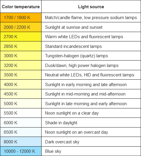
The effects of light of different CCTs and intensities on human biological processes are a spectral response of the circadian system developed under the influence of the natural sequence of day and night. In the course of human evolution, the dynamics of natural daylight established the human circadian rhythm which is set to release melatonin after sunset and suppress melatonin production throughout the day. While cool white light is needed during the daytime from a performance and productivity perspective, nighttime exposure to cool white light will disrupt the body's circadian rhythm. Exposure to blue-rich high CCT light during the night blocks the scheduled release of melatonin. Circadian disruption is linked to increased incidences of diseases in modern society.
The introduction of fluorescent lamps was a disaster in the history of artificial lighting. It makes a large number of populations in the world get accustomed to extremely high CCT (above 6000 K) light during the night. The bright white light with a strong blue tint induces acute melatonin suppression for a large part of the night, making these populations exposed to the risk of circadian disruption and subsequent health effects. Outside the United States, some European countries and Japan, many people take the fluorescent white (6000 - 6500 K) as the standard white and continue to use this range of CCT for residential lighting in the era of LED lighting. What they don't know is exposure to light in this CCT range not only compromises their circadian rhythms, but also make them more susceptible to blue light hazard, a photochemical damage of the retina.
In the United States, cool white light is defined as white light with a CCT of approximately 4000 K or slightly greater. In whatever general lighting applications, CCTs above 5000 K are rarely used. In China, light in the 6000 - 6500 K range is termed cool white and this CCT range is widely used in residential, commercial and industrial applications. While consumers are unaware of the hazard of high CCT lighting, lighting manufacturers in China never attempted to persuade consumers to stay away from high CCT lighting. In fact they love using high CCT LEDs because, when compared to lower CCT LEDs, these LEDs have a lower cost and a higher efficacy, and they also produce less thermal stress.
In the process of photoluminescence, Stokes energy losses occur when shorter wavelength photons (blue photons) are converted to longer wavelength photons and the lost energy is converted into heat. The higher the CCT, the less Stokes losses occur since only a small part of blue light is converted into longer wavelength light. On the contrary, lower CCT LEDs have a relatively low luminous efficacy and higher heat flux due to higher Stokes losses. Moreover, to make warm white LEDs, additional red or yellow phosphors have to be added into the phosphor layer, which increases the light source cost. High Stokes losses and additional phosphor cost are also the reasons why most lighting manufacturers are reluctant to use high CRI LEDs.
Lighting Control
The ability to react instantaneously to changes in power input allows the light output of LEDs to be controlled in a very dynamic way. As LED lights are intrinsically electronic systems, controls and dimming can be easily integrated into LED drivers to provide adaptive and dynamic lighting for spaces where flexibility is important and different scenes need to be created. Adaptive lighting with dimmable LED systems not only allows energy savings to be maximized through control strategies such as occupancy control and daylight harvesting, but also enables advanced lighting applications such as human centric lighting which is based on tunable white technology, and atmospheric lighting that uses dim-to-warm technology. Previously, dynamic presentation of lighting scenes requires complex and expensive hardware integration and programming. The marriage of intelligent LED lighting with digital control systems provides a flexible digital lighting platform that can be scaled across a variety of applications to transform environments, deliver spectacle and compose visual drama.The light output of LEDs can be adjusted using AC dimming methods or DC dimming methods. AC dimming use phase control dimmers to chop an AC waveform the input mains voltage signal to reduce power to lighting loads. This type of dimming control was designed for incandescent lights and other resistive lighting devices. Hence phase control dimmers may not be directly compatible with most LED lighting systems except for LED lights powered by linear LED drivers which operate on resistive loads. AC line dimmers includes 2-wire forward phase (leading edge, triac) dimmers, 2-wire reverse phase (trailing edge) dimmers, and 3-wire (switched hot, dimmed hot, and neutral) forward phase dimmers.
DC dimming utilizes constant current reduction (CCR), pulse-width modulation (PWM) or a combination of them to adjust the light output of LEDs. CCR operates by adjusting the current flowing continuously to the LED load to produce a linear change in light output. CCR dimming is essentially flicker-free because the current is steady. PWM dimming works by switching current at a high frequency from zero to the rated output current. The length of the duty cycle determines the light output. Unlike CCR dimming which can result in a slight color shift, PWM drivers can provide a consistent CCT because the LEDs are always powered at their rated current. This feature makes PWM highly desirable for RGB color mixing and CCT tuning applications where accuracy is critical. Since PWM dimming is based on high speed switching, electromagnetic interference (EMI) can be generated. PWM signals can be interfered when transmitted over long wire runs. As such, PWM dimming is not a good fit for remote-mounted systems and applications with strict EMI requirements. On the other hand, CCR drivers have no concerns of dimming-induced EMI and signal loss from long run operation. PWM and CCR are driver-to-LED controls. Dimmer-to-driver control of DC dimming circuitry can be provided through a variety of protocols, such as 0-10V, DALI, DMX, DMX/RDM, and ZigBee.
The trend towards the Internet of Things (IoT) has brought a new perspective for lighting control. The lighting industry is undergoing a radical transformation fueled by the human-centric lighting concept and the tremendous development in IoT-based smart cities, smart homes and building automation. Smart lighting systems increasingly rely on ubiquitous wireless connectivity to implement advanced features. Sensor integration, device interoperability and software development are some of the new challenges being introduced by IoT.


