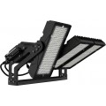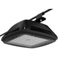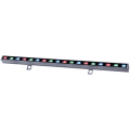

A light emitting diode (LED) is a semiconductor device that generates light using solid-state electronics. LEDs are intrinsically DC devices that only pass current within a single polarity, and are characteristically driven by constant current or constant voltage DC power supplies. There are various LED driver circuit configurations out there on the global market, each of them following different circuit topologies and offering varied advantages. Very generically, LED drivers could be separated in two main groups: linear power supplies and switch-mode power supplies. The switched mode power supply (SMPS) is a widely used type of power converter which has an extensive range of applications. A SMPS may take the form of a rectifier (AC/DC converter), a DC/DC converter, a frequency changer (AC/AC) or maybe an inverter (DC/AC). Switch mode power supplies may have relatively high power conversion efficiency, as opposed to other types of power converters. Switch mode power supplies may also be considerably lighter and smaller than a linear supply owing to the smaller transformer size and weight.
An SMPS achieves these features by switching one or more switching elements such as power MOSFETs at a high frequency (generally tens to hundreds of kHz), with the frequency or duty cycle of the switching being tweaked by using a feedback signal to convert an input voltage to a matching output voltage. The SMPS LED driver circuits may run through the use of pulse-width modulation (PWM), pulse-frequency modulation (PFM) boost, buck, buck-boost or flyback transformer converter circuit topologies that come with reactive components, equipped for storing and converting the electrical energy, for instance inductors and capacitors along with integrated circuits, transistors, diodes and resistors. PWM operation of the SMPS is reliable during higher load conditions but unfortunately drops off in efficient operation under light load condition. PFM control ends up with higher efficiency of the SMPS during light load conditions, but leads to less efficiency at higher load conditions. An SMPS driven by flyback topology typically includes these functional modules: an energy input module, an energy couple module, an energy output module, a feedback module and a controlling module. Switch mode power supplies can productively convert electrical power from the AC source to a load, or perhaps to several different loads, with each matching to a different output. The main transistor of a switching-mode supply can switch between on / off states at a given operating frequency, and voltage regulation can be accomplished by changing the ratio of the on-to-off time of the main transistor.
However, conventional SMPS for LED lighting systems suffer from many disadvantages. SMPS drivers incorporates bulky and unreliable reactive components, which include oscillating coils and electrolytic capacitors so as to convert and store the electrical energy. The electrolytic capacitors are extremely sensitive to the working temperature and have a limited lifetime. The electrolytic capacitor is unreliable and its life span is at least 3-4 times shorter than that of a LED. LED lamps most often have a significantly longer lifespan than their drivers attributable to the presence of electrolytic capacitors in the commercial circuits. An SMPS LED driver produces the predetermined magnitude of DC power by way of a high-speed switching operation to generate much noise, thus resulting in interference, which negatively affects the adjoining circuit elements. EMI should be suppressed and filtered to make certain that it cannot conduct onto the supply lines or radiate out into the surroundings. This often requires a relatively complex and costly EMI filter to be interposed between the AC supply and the device, and frequently the provision of metallic screening around it. Furthermore, the switching loss is the biggest problem. In the switching of the big output driver, the charging and discharging of output driver waste a good amount of energy. All the energy is discharged to the ground in the form of heat. Considering switch loss, the switching frequency cannot be high.
The boost circuit topology comes with the simplest (less parts count), most efficient (Eff=90-95%, typically) and affordable PFC or PWM LED driver implementations, with two main shortcomings: it cannot offer isolation between the input and output circuits and its output voltage is constantly higher than its maximum input voltage. The buck circuit topology, which as well allows for circuits with fewer component counts, is moderately efficient (Eff=85-90%, typically) and cost effective. Nonetheless, it doesn't come with isolation between the input and output circuits, but further, there is a direct current from the high voltage DC source trough the LED stripe to ground which might cause damage to the LEDs in the event the converter's buffer breaks down in a "short circuit" fashion and, its output voltage is often lower than its minimum input voltage. The buck-boost circuit topology overcomes a few of the aforementioned disadvantages by allowing higher, equal or lower output voltage with regards to its input supply voltage amount, operating with good efficiency (85-90, typically) and fewer parts count. However this type of SMPS circuit does not offer isolation between the input and output circuits, it needs complex differential voltage sensing technique of the output V/I parameters (not for SEPIC) because its output circuit carries a different zero volts reference in terms of the input circuit. Additionally, it requires a special "constant Off time" controller IC when it is operating in CCM (Continuous Conduction Mode) and a further power factor correction circuit in AC applications. The flyback circuit topology is the only circuit which, via its two coils flyback transformer, offers complete isolation between its input and output circuits and enables higher, equal or lower output voltage regarding its supply voltage amount. But flyback circuits are way more expensive, and with much more parts count, increased size, reduced efficiency.